A Vector Graphics Renderer — part 1
The is a writeup of a vector graphics renderer I've been working on. It is part of an application engine I made to build GUI and graphics applications. I've been using it mostly on my work-in-progress show-controller, but also in small tools and demos.
Previously all the 2D drawing of the engine was based on Cairo Graphics
. Although Cairo is a reasonable API and a good starting place, I wanted to drop it at some point for the following reasons:
- It's adding a bunch of dependencies that it doesn't even fully needs in my case. You can strip some of these by invoking magic flags during the build process, which really insists that you should include them anyway.
- It is also tedious to embed a custom-built version of Cairo in a self-contained application, since by default it links against those dependencies dynamically and searches them at predefined absolute paths.
- It had performance issues with either the software rendering backend, or the Quartz Graphics backend. And OpenGL backend seems to exist but I wasn't able to build it or to find a comprehensive documentation on it. I'm also not sure if the performance is really due to the backend, although I guess it could help.
- I wanted to learn more about graphics and see what goes into making a vector graphics library.
Anyway, I decided to replace my Cairo-based renderer with my own handmade vector graphics renderer, using OpenGL. I'm going to make a few posts about it, covering how I handle path stroking, filling, text rendering, and performance topics.
Much like other 2D vector graphics libraries, Top's renderer is built around the concept of a graphics context, which holds some properties such as the current color, the line width, the font size, etc. and paints into a surface, typically a window. It also exposes an API to build a path consisting of connected segments and curves, and some drawing functions that draw the outline of the path or fill the area contained by it.
So the goal here is to take a path as input, and output a set of triangles to be sent to the GPU. Later, we could try to push more work load into the shaders, but for now that part is done in the CPU. In this post I will give an overview of the path construction and the stroking mechanism.
Paths and stroking API
The path is defined as a list of path elements. I'm using a list_info structure much similar to linux linked lists, and I just embed a list_info member inside the structures I want to put in a list.
A path element can be of type MOVE_TO, which is used for the starting point, LINE_TO, which describes a straight line from the current point to the next point p, and CURVE_TO, which describe a cubic Bézier curve from the current point to the next point p using the two control points c1 and c2.
The graphics context is a structure that, among other properties, hold a graphics_path. You can use the following functions to sequentially build a path:
Those functions create a path element and append it to the path's elements list:
It's pretty straightforward, the only particularity here being the use of GraphicsContextScratchAlloc(), which gives us a bloc of memory from a “scratch buffer” owned by the graphics context to hold transient state and perform temporary calculations, avoiding a frequent use of malloc/free.
Now we introduce three other functions that sets the current color, line width, and curve tolerance. That last parameter determines the precision needed when approximating Bézier curves.
Finally we have a functions which is used to stroke the path with the currents properties:
Piecewise approximation of Bézier curve
The first step involves replacing the Bézier curves elements of the path with a piecewise approximation consisting of line elements. Along the way we also eliminate duplicated points, which saves us unnecessary calculation and edge-cases special handling.
A cubic Bézier curve is a parametric curve defined by the equation:
Where C0, C1, C2, C3 are the control points and t varies from 0 to 1. When we encounter a CURVE_TO element, we approximate the Bézier curve to replace it by a sequence of LINE_TO elements by calling GraphicsPathBezierToLines(), whose prototype is the following:
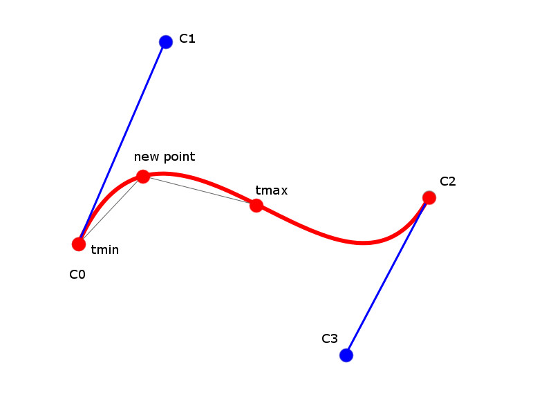
This function takes the four control points of a cubic Bézier curve and a tolerance value, and fills a path with an estimate of that curve composed of line segments. It is effectively a stub that calls a recursive version, which evaluates the curve portion starting at an element elt for t = tmin and ending at the next element, with parameter t = tmax:
In that function we evaluate the point on the curve which is “halfway” between our two end-points, using the equation of the cubic Bézier curve. If the distance from this point to the middle of the segment between our two end-points exceeds the tolerance value, we break our current segment in two, joining our end-points to the point we just evaluated. We then repeat the operation for both segments.

Generating triangles for the renderer
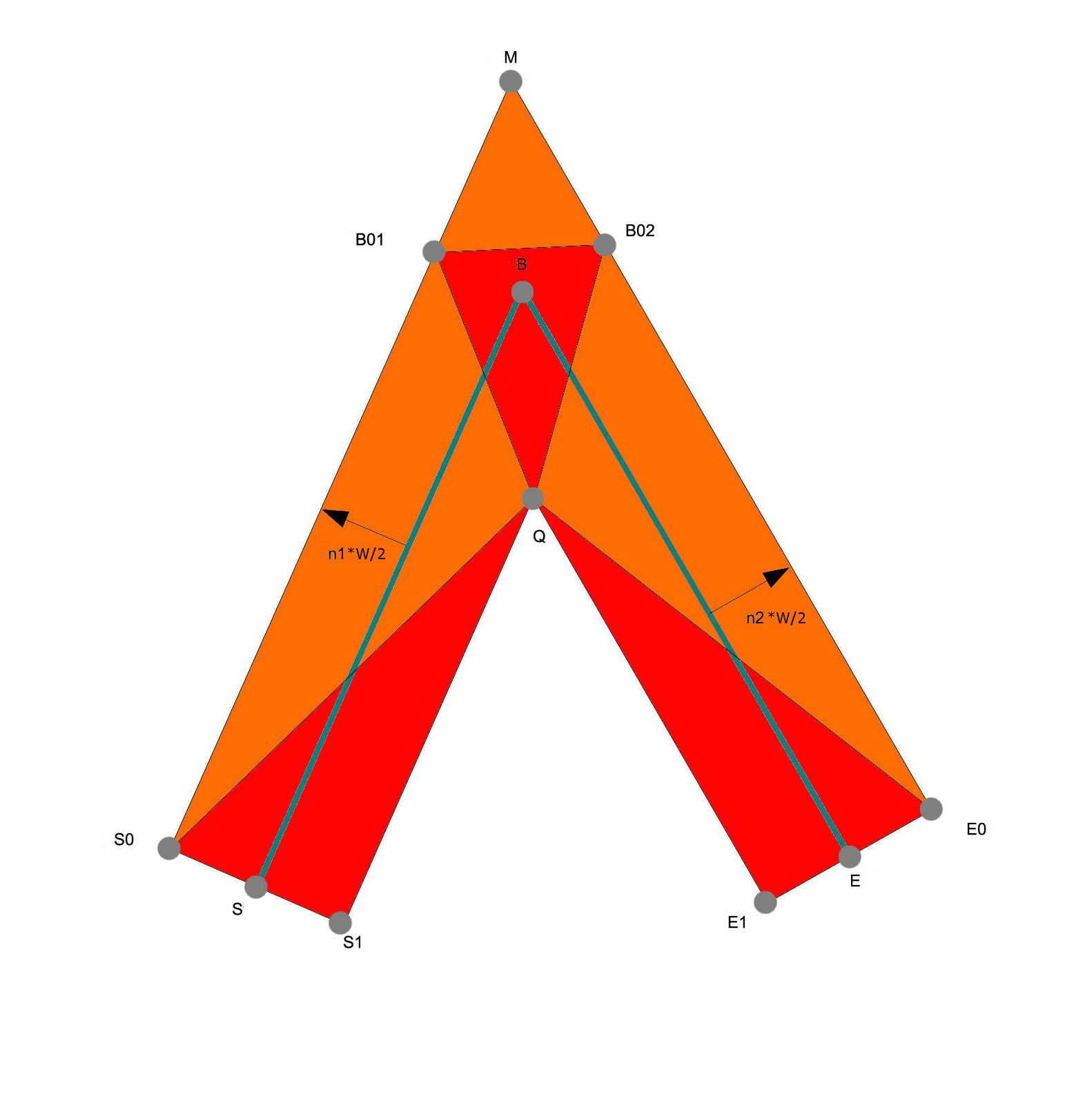
We now proceed to stroke the path. For each path element, we have three points to consider:
- S, which is the middle of the segment joining the destination points of the last-processed and the current elements. When processing the first element of the path, we define the last-processed element to be the last element of the path if the path is closed, otherwise we set S to be the destination point of the first element.
- B, which is the destination point of the currently processed element.
- E, which is the middle of the segment joining the destination points of the current and the next elements.
From these points we compute n1 and n2, the normals to [S;B] and [B;E], as shown on the figure. If the cross-product of these normals points along negative z, the normals are pointing to the outside of the angle formed by S, B, E. Otherwise, they are pointing inside, and we multiply them by − 1 to always have them pointing outside. We now compute S0, S1, B01, B02, E0, E1, Q and M as shown on the figure below:

Which leads us to the following computation:
where halfW is half the current line width. M is the intersection between (S0;B01) and (E0;B02), so
where
and finally,
Joint types
If we want to render miter joints, we can send the following triangles to our OpenGL renderer (details on how we implement that will appear in a next post):
We can render a bevel joint by sending the following triangles to our OpenGL renderer:
When the angle between the two segments of the joint is very small, the distance between M and B, a.k.a the miter excursion, grows towards infinity. We thus define a miter excursion threshold: when the miter excursion is higher than the threshold, we falback to the bevel joint case.
Finally, if there is no next element and the path is not closed, ie. E == B we draw a butt cap:
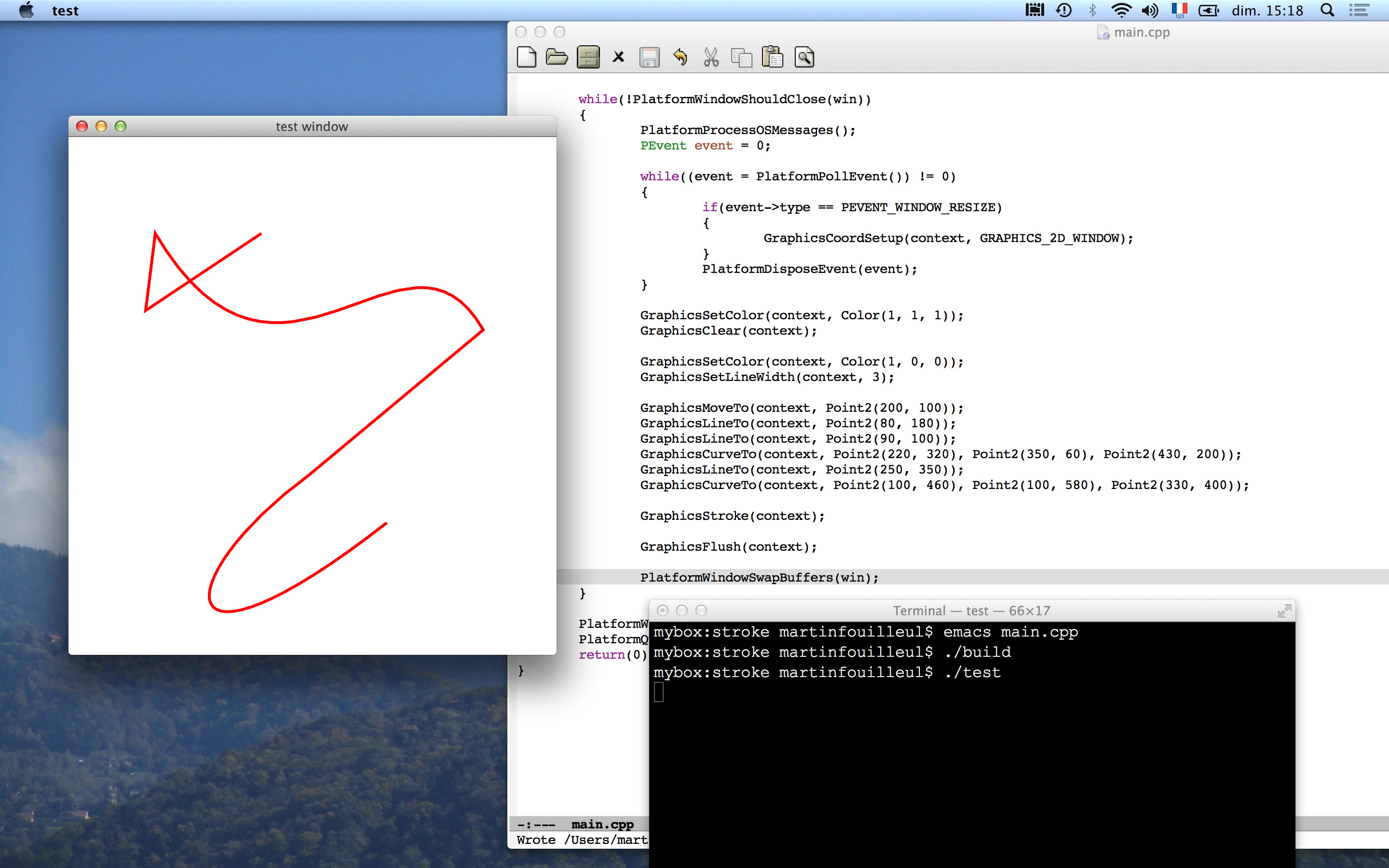
The screenshot below shows an example of a stroke:

This wraps up the overview of our first drawing function. In the next post I will show how we triangulate any (non intersecting) polygon in order to fill the area inside our path.